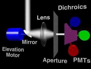
An aperture eliminates all but a tiny portion of the information, and this light is split (in color versions) by dichroic prisms into a red, green, and blue beam. Each of these is then measured by a photo detector, amplified, converted to digital information, and stored as a pixel in an image.
In practice, and since this "research" was funded out of spare/scrounged parts, the process works like this: The elevation motor was initially driven by a commercial stepper controller. You fed it pulses to count up or down, and the motor turned in 1/200th rev. steps clockwise or counter-clockwise. The mirror was a 3/4" mirror from a cheap plastic dental inspection mirror I had in my toolbox. The primary lens was a 1-3/4" lens much like a magnifying glass. I used a 1P21 photomultiplier I just happened to have left over from a previous project. It came with a neat little integral socket/power supply, so I didn't have to build a 2Kv supply. The whole thing sat on a larger step motor driven the same way. That gave me 200 steps of azimuth. With my trusty IBM PC-XT, I could hook the printer port up to the two motors, and sample a 200x200 monochrome image of the environment.
I wrote code in pascal (I know, I know, yuck!) to control the steppers, sample the video, and display on a framebuffer. I need to digress a bit about that too. In 1984, there weren't any nice 24-bit PC framebuffers. I ended up using a really bizarre box called an Innovion. It was a full 24-bit framebuffer system, but it was controlled by an internal 6502, and came with a really lame paint package. I ripped out the parallel port chip, and installed instead a socket that went to an interface card I built for the XT, and I talked to it directly with portout() statements.
The first issue that came up was the inadequate resolution you get from 200x200 steps. Stepper motors are basically 4-phase AC motors. They are limited to 200 steps because they only have 200 poles internally, but that doesn't mean they can only be positioned at 200 locations. I had some nifty modules that took a 12-bit number and gave an analog sine and cosine voltage, with one cycle being divisible by 4096. So I built a card cage, installed a sine/cosine module per motor, and built motor drivers to take the +/- sine and cosine and drive the four windings of each motor. A picture of the electronics side of my setup can be seen here. Thus, I increased the possible resolution from 1/200 revolution to 1/819,200 revolution.
I made some test scans. They looked really bizarre. It was like M.C. Escher's twisted perspectives, but yet if you looked at any small part of the image, everything was normal. I got excited. I wanted to make color scans, but I didn't have three photomultipliers. I rewrote the programs to let me scan the scene three times with color filters over the lens and built up color images. They worked. Unfortunately, I didn't save any original images from scanner #1. But I was encouraged enough that I could see the need to have three sensors.
So, I started building Scanner #2.